The main challenge for the REDTOP experiment is the rejection of the background since, at the energy where the experiment will run, the ratio of η-production to inelastic proton scattering is about 1:200. Of course, background events will differ significantly from signal events, both kinematically and topologically. To optimize the signal-to-noise ratio, the experiment has been designed with the following key features:
- The target is sparsified, consisting of multiple elements distributed along the beam axis. This configuration reduces pile-up, as signal and background events are likely to occur in different target elements.
- Since most of the events relevant to the search for New Physics involve fast leptons, the apparatus is optimized for particle identification (PID). By appropriately tuning the refractive index of the Čerenkov radiators, background events—typically composed of hadrons in the final state—will produce no detectable signal, while the faster leptons can be efficiently identified.
- Given the expected hadronic interaction rate of approximately 700 MHz, the detector is designed with high granularity and fast response to minimize pile-up from multiple beam interactions.
The Target Systems
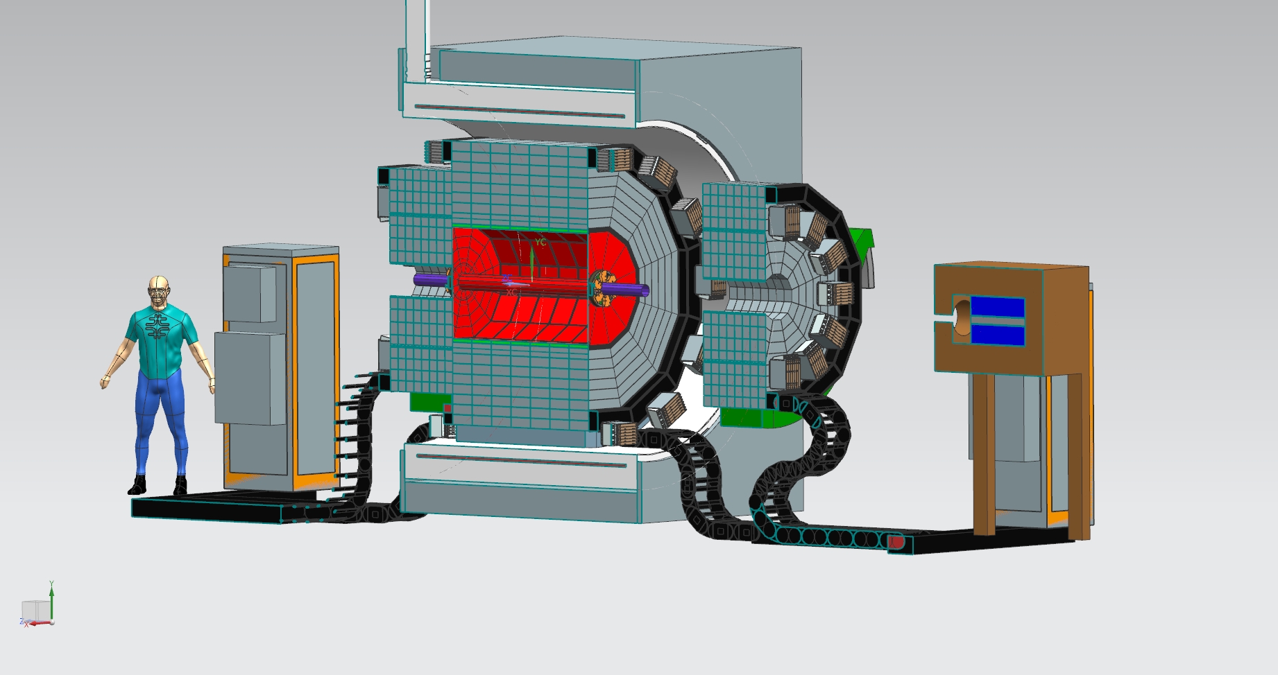
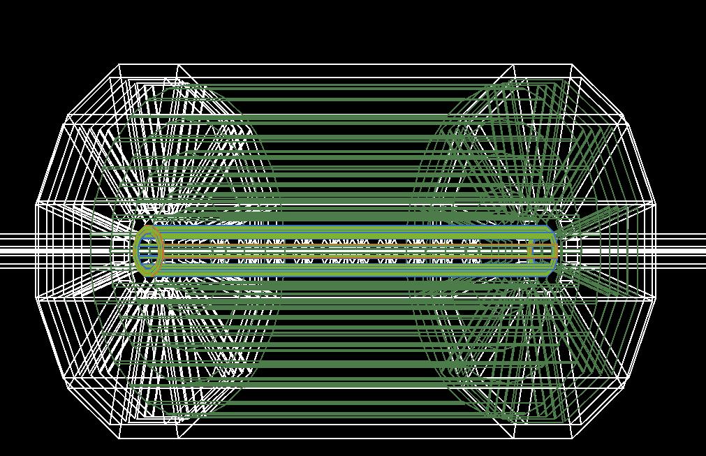
The target system (indicated by the red circle in the figure above) consists of ten circular foils made of either beryllium or lithium, each approximately 0.33 mm thick for Be (0.75 mm for Li) and with a diameter of about 1 cm. The foils are mounted along the beam axis inside a beam pipe constructed from either carbon fiber or beryllium. The beam pipe serves the dual purpose of maintaining the vacuum and providing mechanical support for the aerogel layer attached to its external surface.
A proton with a kinetic energy of 1.8 GeV has a 2.5% probability of undergoing an inelastic interaction in any of the target foils. The probability that such an interaction results in η-meson production is approximately 0.47%. Given an average beam intensity of 1011 protons/sec, the expected η yield from the target system is on the order of 1×10¹⁴ over a three-year run
The Vertex Detector
The vertex detector serves three primary functions:
a) contributing to the reconstruction of charged particle tracks originating in the target region;
b) rejecting photons that convert within the target materials; and
c) reconstructing tracks with very low transverse momentum.
One detector technology option is currently under investigation for the vertex system: a super-thin, HV-MAPS silicon sensor.
OHV-MAPS silicon sensor
The vertex detector represented by the innermost volume in Fig. 1) has four main tasks: a) identifying events with a detached secondary vertex; b) contributing to the reconstruction of charged tracks originating from the target; c) rejecting photons converting in the target; and d) reconstructing tracks with very low transverse momentum. The most critical aspects of REDTOP vertex detector are related to the material budget and to its proximity to the interaction region. The former needs to be kept as low as possible to reduce multiple scattering, which, in the momentum range of interest for REDTOP, is the major source of resolution loss.
The main requirements for the vertex detector are
- spatial resolution near the IP better than 20 μm,
- material budget: <0.1% X0/layer, and
- timing resolution of a few ns.
Radiation hardness up to ∼ 5 × 10⁶/cm2/s “1-MeV ENF ” is also an important aspect of this subsystem. The above requirements are similar to those of the pixel tracker of the Mu3e experiment at PSI (muon stopping rate ≃ 100M Hz in phase-1 and ≃ 2000M Hz in phase-2 vs inelastic event rate ≃ 500−700 M Hz for REDTOP; maximum track momentum ≃ 53 M eV /c vs ≃ 1.1 GeV /c for pions and ≃ 2.2 GeV /c for protons in REDTOP). Recent demonstrations have shown that the technology can achieve a time resolution of 6−8 ns with an appropriate time-walk correction [rudzki2021mu3e], which also aligns well with the requirements of REDTOP. Therefore, we adopt the same HV-MAPS technology as
Mu3e, based on the MuPix sensor [MU3ERP2012].
The vertex detector proposed for REDTOP will consist of three layers of HV-MAP sensors for the barrel and for the endcaps with a coverage >90% of full solid angle. The innermost layer is located at a distance of 2.4 cm from the beam axis, while the radius of the outermost layer is ∼ 4.2 cm, corresponding to a solid angle coverage of ∼ 91%. The material budget of the vertex detector is ≃0.1% of X/Xo per layer.
The Central Tracker.
One options iscurrently being investigated for the central tracker:a thin LGAD silicon tracker.
The LGAD tracker
A silicon tracker based on Low-Gain Avalanche Diode (LGAD) technology is being evaluated . Simulations performed with GenieHad and Geant4 indicate that, in these cases, the average particle multiplicity per background event is fewer than ten—well within the reconstruction capabilities provided by the high granularity of the LGAD tracker.
This detector concept is especially well suited for operation at PIP-II, where the produced particles have lower momenta. Additionally, the ³He ions required for η-meson tagging at PIP-II can be efficiently reconstructed with the LGAD system.
The proposed tracker, a scaled version of the SiD vertex detector, occupies the same volume currently allocated to the OTPC. It comprises five polyhedral layers in the barrel region and four planar layers in the endcaps, covering a total instrumented area of approximately 11 m². The sensors feature a 3-mm pixel pitch, corresponding to about 17 million channels and requiring more than 850 readout ASICs.
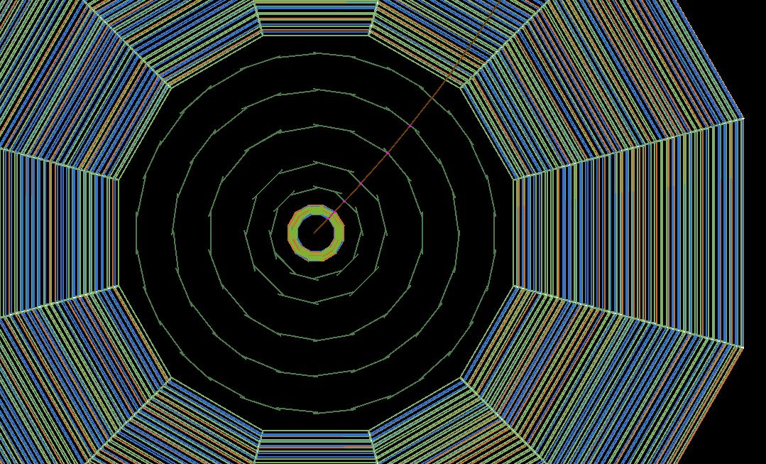
The tracker occupies the same spatial region as the OTPC. It consists of five polyhedral layers for the barrel and four planar layers for the endcaps. The total area instrumented is about 11 m2. The pixels have a pitch of 3 mm. The total channels are about 17×106 and require more than 850 readout asics.
The Cerenkov TOF
A Cerenkov radiator is located immediately inside the calorimeter for the Central Tracker option 2 (LGAD detector). It is made of small cubes of borosilicate glass with a side of 3 cm. The Cerenkov light produced in each cube by the particles escaping the Central Tracker are read-out by a SiPM. The detector has two purposes:
- select the particles fast enough to make Cerenkov light (Cerenkov threshold detector);
- measure the TOF of such particles.
That information is used in the Level-0 trigger to reject background events with slow particles.
The Cerenkov Radiators of the OTPC
Two Cerenkov radiators are present in the OTPC (option I above):
- A double aerogel cylinder, about 3 cm thick at the inner wall, supported by the beam pipe (the dark green ring in the picture above) . The innermost aerogel has nD =1.22 while the outermost has nD = 1.3;
- low-pressure nitrogen gas filling the rest of the volume of the OTPC. The pressure is adjusted in order to have nD = 1.000145.
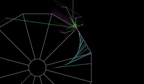
Muon particles with momentum larger than 160 MeV will radiate only in the aerogel. The radius, the center and the skewness of the ring will help to determine its velocity. The dual refractive systems will help in discriminating the pions from the muons. On the other side, electrons and positrons will radiate in aerogel as well as in the gas. The ring produced by such light particles has a radius mostly independent from their velocity and much larger than that of the muons. That feature will provide a particle identification for electrons vs. muons. Furthermore, the Cerenkov photons radiated from the gas will generate a characteristic pattern in the photo-sensors. From the analysis of that pattern, one can estimate the momentum of the electron and its position in space. The picture below shows what happens in REDTOP’s OTPC when a 100 MeV electron (red track) travels trough the gas in a 0.6 T magnetic field. Several Cerenkov photons (cyan tracks) are generated and detected by the optical sensors surrounding the gas.
The ADRIANO2 and ADRIANO3 Multiple-Readout Calorimeters
REDTOP calorimeter plays an important role in searches for physics BSM. It has two main roles: a) measuring the energy of neutral particles with sufficient precision so that the rare decays of the f η and η’ mesons could be disentangled from the backgrounds; b) contributing to the PID systems to separate EM particles from proton and neutrons. It also participates in the Level-0 trigger, therefore, it needs to be very fast.
The main requirements for REDTOP Calorimeter are summarized below:
- Energy resolutionσ(E)/E=3%/√E
- Particle Identification (PID) between electromagnetic and hadronic showers with an efficiency better than 99%;
- Time resolutions <80psec;
- Detector response within ~100nsec
The first requirement is due to the necessity to reconstruct π0‘s generated in the target and the decaying into two photons and γe+e–as their decay products contribute to the combinatoric background feeding in the signal. Furthermore, several decays of the η/η’ mesons contain γ’s or π0‘s. Therefore, an higher energy resolution of the latter will allow a more efficient reconstruction of events associated to η/η’ decays.
Particle Identification is important to reduce the hadronic background. Some form of PID needs to be implemented already in the level-0 trigger, to reduce the number of non- η/η’‘ events to a more manageable level. The requirement on the time resolution is part of PID, since baryonic particles (which constitute the largest fraction of particles generated in the primary interaction), have a much slower time-of-Flight (TOF) compared to the η/η’ decay products. Finally, a fast detector response is necessary considering the expected event rate in the calorimeter from inelastic p-Li events is of the order of 0.5 GHz. Assuming a pipeline with a depth of fifty, the event needs to be processed by the Level-0 trigger in less than 100 nsec.
The technologies chosen to fulfill the above requirements are a particular implementation of multiple-readout calorimetry, called ADRIANO2 and ADRIANO3, briefly described below.
The REDTOP calorimeter is divided into two sections. The innermost section (about 40 cm in depth) is designed as a high-granularity, integrally active dual-readout calorimeter: ADRIANO2, constituted by alternated tiles of lead-glass and scintillating plastic optically separated and read-out individually. Its main task is to reconstruct EM showers and measure the energy of photons and electrons. The outermost section implements an ADRIANO3 triple-readout calorimeter. The latter has a similar layout as the innermost section but includes a third readout: a Gd-doped glass RPC along with layers of passive material to reduce the nuclear interaction length of the detector so that showers generated by the hadrons are fully contained in the overall depth of the calorimeter (about 80 cm). The Gd-doped glass RPC ‘s are sensitive to neutrons, which are the third independent component of an hadronic shower.
Both calorimeter sections are part of the PID systems.
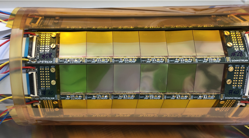
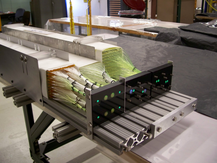
Dual-readout and triple-readout calorimetry are novel detector techniques that has received good attention in the last few years. One version of the latter, named ADRIANO (A Dual-Readout Integrally Active Non-segmented Option), has been under development at Fermilab by the T1015 and T1604 Collaboration for many years. The picture below shows three ADRIANO prototypes tested at FTBF in 2015.
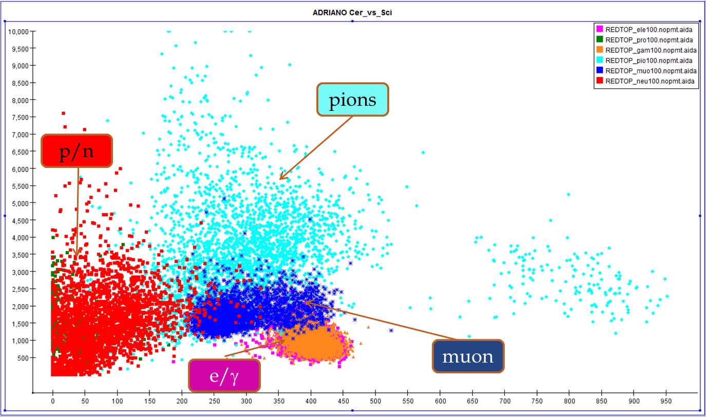
ADRIANO2 technique is based on the two simultaneous measurements of the energy deposited by a hadronic or electromagnetic shower into two media with different properties. The first medium is usually a plastic scintillator (or any substance producing scintillating light). Consequently, any charged particle depositing energy in that medium will produce scintillation and will make a signal in the corresponding electronics. The second medium is usually a heavy glass with high refractive index (nD >1.8) and high density (ρ >1.8). This medium will only be sensitive to charged particles with large velocity, such that light is emitted via the Cerenkov effect. Consequently, only the charged electromagnetic component of the shower (namely: electrons and positrons) or photons producing pairs will produce a signal in the corresponding electronics. Furthermore, the high density of the medium will make it an ideal integrally active absorber for all particles impinging on the detector. Summing the Cerenkov (C) and the scintillation (S) signal one has the total energy of the detected particle. Furthermore, by comparing the scintillation (S) vs. the Cerenkov (C) signals one also has information about the ID of the particle which generated the shower. This is shown, for example, in the plot below for simulated particles with Ekin=100 MeV.

The main advantage of using an ADRIANO2 and ADRIANO3 calorimeters for detecting photons from the η decay is that the background from most neutrons entering the detector can be easily rejected. Furthermore, the different behavior in terms of S vs. C of muons and pions will help the double aerogel systems in disentangling the signals from the two different types of particles. The ADRIANO calorimeter corresponds to the outermost blue dodecagon in the detector sketch at the beginning of this page.
ADRIANO2 and ADRIANO3 represent a novel implementation of the older ADRIANO technique. The building block of ADRIANO2 is a pair of, optically separated, plastic, and lead glass tiles each with a side of 3 cm. The lights generated by particles going through is collected with SiPM directly coupled to the tiles. The advantages vs the original technique are several:
- The high granularity in 3-D of the detector helps in disentangling complex events, with high multiplicity showers;
- Particle-flow algorithms can be applied to improve the energy resolution of the calorimeter;
- The prompt Cerenkov light generated inside the glass tiles is read-out immediately, without wavelength shifting, providing fast timing information to the trigger systems and complementing the dual-readout based, PID with TOF measurements.
In the case of ADRIANO3, a layer of Gd-doped glass RPC is added to improve the sensitivity to neutrons.
The Muon Polarimeter (optional)
The muon polarimeter (the green bars in the detector sketch) is an array of plastic scintillators inserted between the inner and the outer shells of ADRIANO. They have the task of counting the number of electrons and positrons emitted when a muon is stopped inside the ADRIANO calorimeter. This happens in a short range of depths after the muon has lost all of its energy. The initial polarization of the muon is not lost in this process since the ADRIANO lead-glass is homogenous and isoscalar. If the muon carries a non-null polarization, the electrons (or positrons) are emitted non-isotopically in the solenoidal magnetic field. The muon polarimeter will count those electrons: any unbalance in the left-right or front-backward counting is associated with a non-null transverse or longitudinal polarization of the initial muon.
The Photon Polarimeter (optional)
The photon polarimeter (the purple ring in the sketch of the detector) works on the same principles as the muon polarimeter. A 5 mm thick scintillating plate is inserted inside the volume of the OTPC. When a photon hits that material it has a finite probability of converting into a e+e- pair. If the circular polarization of the photon is zero, then the decaying pair has an isotropic distribution inside the 0.6 T solenoidal magnetic field. Otherwise, the asymmetry of the direction of the e+e- pair will provide an estimate of the polarization of the initial photon.